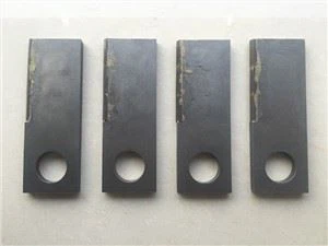

CNC (Computer Numerical Control) machining is a pivotal process in modern manufacturing, allowing for the creation of highly precise and complex parts. As a reliable CNC machining parts supplier, ensuring the quality of the parts through proper inspection methods is of utmost importance. In this blog, we will delve into the common inspection methods for CNC machining parts to help you understand how we maintain high - quality standards.
Visual Inspection
Visual inspection is the most basic yet crucial inspection method for CNC machining parts. It is often the first step in the quality control process. This method involves using the naked eye or simple magnifying tools to check for obvious defects such as surface scratches, cracks, burrs, and unevenness.
For example, when inspecting Aluminum Alloy Machined Boss, a scratched surface may not only affect its appearance but also potentially reduce its anti - corrosion ability and mechanical performance. Through visual inspection, our quality control team can quickly identify such surface - level issues and take immediate action, either by re - machining the part or discarding it if the defect is severe.
Visual inspection also helps in verifying that the part conforms to the overall design requirements in terms of shape and rough dimensions. We look at whether the part has the correct general contour, number of features, and basic symmetry. However, it should be noted that visual inspection has its limitations. It can only detect relatively large and visible defects, and it may not be sufficient for detecting internal or microscopic flaws.
Dimensional Inspection
Dimensional accuracy is one of the most critical aspects of CNC machining parts. A slight deviation from the specified dimensions can lead to improper fitting, reduced functionality, or even complete failure of the final product.

Caliper Measurement
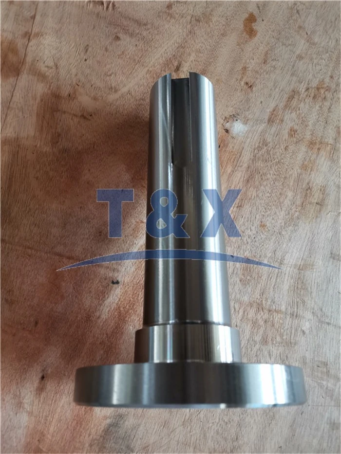
Calipers are one of the most commonly used tools for dimensional inspection. Vernier calipers and digital calipers can measure the outer diameter, inner diameter, depth, and step dimensions of a part with relatively high accuracy. For instance, when inspecting Machined Pins Construction Machinery Parts, we use calipers to measure the diameter of the pins at different positions to ensure they meet the design requirements. Digital calipers are especially popular due to their ease of use and the ability to display measurements directly in digital format, reducing the potential for human reading errors.
Micrometer Measurement
Micrometers offer even higher precision than calipers. They are typically used for measuring very small dimensions with an accuracy of up to a few micrometers. For parts with tight tolerance requirements, such as the shafts of precision instruments, micrometers are indispensable. When measuring the diameter of a Precision Machining Drive Shaft, a micrometer can provide the accurate data needed to determine if the part is within the specified tolerance range.
Coordinate Measuring Machine (CMM)
A CMM is a highly advanced and accurate dimensional inspection tool. It can measure the three - dimensional coordinates of points on the surface of a part, allowing for comprehensive dimensional analysis. CMMs are equipped with a probe that can touch the part's surface at different points, and the data collected is then processed by software to generate detailed dimensional reports. This is particularly useful for complex - shaped parts where multiple dimensions and geometric features need to be measured simultaneously. With a CMM, we can precisely measure the position, orientation, and form of various features on CNC machining parts, ensuring their compliance with the intricate design specifications.
Geometric Inspection
CNC machining parts often have specific geometric requirements, such as flatness, straightness, roundness, cylindricity, and perpendicularity. Geometric inspection is used to verify whether these geometric parameters meet the specified standards.
Flatness Inspection
Flatness inspection is essential for parts that need to have a flat surface for proper functionality or mating with other components. One common method is to use a surface plate and feeler gauges. The part is placed on the surface plate, and feeler gauges are inserted between the part and the surface plate to measure the gap at different points. If the gap exceeds the allowable tolerance, the part's flatness is not within the required range.
Roundness and Cylindricity Inspection
For cylindrical parts like shafts and pins, roundness and cylindricity are crucial. Roundness refers to how closely the cross - section of a cylinder approximates a perfect circle, while cylindricity considers the shape of the entire cylinder along its axis. Specialized roundness and cylindricity measuring instruments are used to perform these inspections. These instruments rotate the part while measuring the radial distance from a fixed point, and the data is analyzed to determine the roundness and cylindricity errors.
Perpendicularity Inspection
Perpendicularity is important when two surfaces or features of a part need to be at a right angle to each other. A square or a coordinate measuring machine can be used to check perpendicularity. For example, when inspecting a part with two intersecting surfaces, a square can be placed against one surface, and the gap between the square and the other surface is measured to assess perpendicularity.
Material Inspection
The material of a CNC machining part is a fundamental factor that affects its performance and durability. Material inspection aims to verify the material composition, hardness, and other properties of the part.
Material Composition Analysis
X - ray fluorescence (XRF) and energy - dispersive X - ray spectroscopy (EDS) are commonly used methods for analyzing the material composition of CNC machining parts. These techniques can quickly and non - destructively determine the elemental composition of the material, helping to ensure that the part is made of the correct material grade. For example, for aluminum alloy parts, XRF can accurately identify the percentage of different alloying elements such as copper, magnesium, and zinc, ensuring that the alloy meets the required specifications.
Hardness Testing
Hardness is an important property of a material, as it affects the part's wear resistance and strength. There are several hardness testing methods, such as the Rockwell hardness test, Brinell hardness test, and Vickers hardness test. Each method has its own advantages and is suitable for different types of materials and part sizes. For instance, the Rockwell hardness test is relatively quick and easy to perform and is commonly used for general - purpose hardness testing of metals. By performing hardness testing on CNC machining parts, we can ensure that the material has the appropriate hardness for its intended application.
Surface Roughness Inspection
Surface roughness can significantly impact the function and performance of CNC machining parts. For example, a rough surface may increase friction, reduce sealing performance, or even cause corrosion.
Profilometer
A profilometer is a commonly used instrument for measuring surface roughness. It works by moving a stylus along the surface of the part, and the vertical movement of the stylus is recorded to generate a profile of the surface. The profilometer can then calculate various surface roughness parameters, such as Ra (arithmetical mean roughness) and Rz (maximum height of the profile). By measuring the surface roughness, we can ensure that the part meets the required surface finish standards.
Optical Surface Roughness Measurement
Optical methods are also used for surface roughness inspection. These methods use light to measure the surface topography without physical contact. They are particularly useful for measuring the surface roughness of delicate or small - sized parts, as they do not damage the surface. Optical surface roughness measurement can provide high - resolution and accurate data, helping us to maintain excellent surface quality of CNC machining parts.
Non - Destructive Testing (NDT)
Non - destructive testing is used to detect internal defects in CNC machining parts without damaging the part itself. This is crucial for parts that need to withstand high stresses or have critical safety requirements.
Ultrasonic Testing
Ultrasonic testing uses high - frequency sound waves to detect internal flaws such as cracks, porosity, and inclusions. A transducer is used to send ultrasonic waves into the part, and the waves are reflected when they encounter a defect. By analyzing the reflected waves, we can determine the location, size, and type of the defect. Ultrasonic testing is widely used for inspecting thick - walled parts and welded components.
Magnetic Particle Testing
Magnetic particle testing is used for ferromagnetic materials. The part is magnetized, and magnetic particles are applied to the surface. If there is a surface or near - surface defect, the magnetic field is distorted, and the magnetic particles will accumulate at the defect site, making it visible. This method is relatively simple and cost - effective for detecting surface and near - surface cracks in ferromagnetic parts.
Conclusion
As a CNC machining parts supplier, we understand that the quality of our products is the foundation of our business. By using a combination of these common inspection methods, including visual inspection, dimensional inspection, geometric inspection, material inspection, surface roughness inspection, and non - destructive testing, we can ensure that our CNC machining parts meet the highest quality standards.
If you are in need of high - quality CNC machining parts for your projects, we invite you to contact us for procurement and negotiation. We are committed to providing you with the best parts and services.
References
- "Manufacturing Engineering and Technology" by Serope Kalpakjian and Steven R. Schmid.
- "Quality Control for Machining Processes" by various industry experts in manufacturing quality control.
- Technical documentation from leading inspection equipment manufacturers.